Many centuries ago, human being found out the power of steam, but using industrial steam boilers started from 1712. They were made of lead or wood producing pressure a little more than atmosphere. In 1725, Histech boilers with steel riveted plates and proportional pressure came into use.
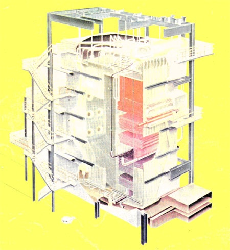
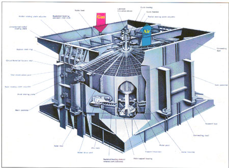
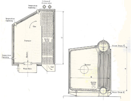
(Figure 1) Schematic Section of a Boiler
By passing the time, it was determined that the best way of using boilers scientifically is to make them circular. In 1795, by producing rolled plates, circular boiler was made too. Water Tube boilers were made in 1873 (Figure 1). Water flows in slant pipes where the heat absorbs. Regarding extending the surface the heat will be exchanged in the best way.
By extending other parts such as super heater, deaerator economizer and air heaters, and so on, gradually, the primary steam boilers changed to current boilers with more capacities. Boilers advancement processes are mentioned below:
1. Temperature increase
2. Pressure increase
3. Boiler steam outlet increase
4. Efficiency increase
5. Easy to control
6. Reducing manufacturing, operation and maintenance expenses
7. Boiler lifetime increase
Boiler kinds:
Boiler duty is to turn liquid (water) into super saturated steam, but in industry, all devices turning liquid to super heated steam are called boiler.
Boilers are being used in steam production units for general, electrical and industrial uses, and depend on their planning can make use of charcoal, mazut, gas, oil and natural gas as their fuel.
Based on different parameters, boilers classification is as bellow:
Fossil Fuel Boilers:
All industrial boilers Iran use fossilized fuels. Using fossilized fuels for producing electricity forms much carbon dioxide because the heat generated from burning the fossil fuels is three times more than the produced electrical energy. Upon the negative effects, the fossil fuels have on our life and environment, it is recommended to reduce using fossil fuels.
The followings are different fossil boilers:
1. Vessel boilers:
This kind of boilers consists of closed vessel in which heat exchange occurs out of it and water vaporizes in the vessel. Their efficiency is low -about 30%-, which are used just in industries with low-pressure steam.
2. Fire Tube Boilers:
In these boilers, tubes are coated with water and produced gases pass through the tubes. Heat exchange occurs between water and products. Furnace can be in or out of the boiler. Fire tube boilers efficiency is about 70%, which are used for steam production in low-pressure units.
3. WATER TUBE BOILERS:
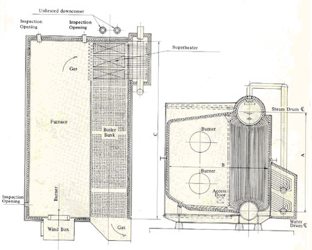
In different kinds of these boilers (figure 2), heat exchange occurs by contacting the produced gases with the outer surface of tubes containing Water and steam and in conducting, replacement and radioactive ways. Small Diameter of the steam and water tubes that reduces thermal stresses on tubes is the advantage of these boilers to fire tube ones, which consequently are used in high-pressure industries. Their efficiency is about 85 to 95%.
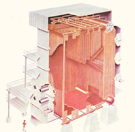
(figure 2)
A water tube boiler consists of combustion chamber with tubes, steam and water headers and drums, super heaters, air heaters, economizer and preservers.
In this boilers, integrated fin coated vertical tubes are used since water tubes are under high thermal charge, pressure and temperature stresses effects should be designed precisely. Water tubes are assembled in vertical mode in combustion chamber, which are welded in stubs on upper and lower sides of headers. Headers reduce the number of tubes connected directly to drum. Temperature distribution in water tubes depends on heat transmission coefficient, thermal charge amount, thermal conduction coefficient, dimensions, and tubes engineering and fin structures. Fins cause equal distribution of thermal charge on tubes, reduce boiler heat gradient in one hand, and increase the heat exchange level, which causes more heat exchange on the other hand.
3.1. ONCE THROUGH BOILER:
Are non-drum boilers with super critical pressure, which are called Benson. Combustion chamber and wall tubes assembly are planned in a way that wall tubes feeding water passes the combustion chamber and wall tubes, and then vaporizes and conducts directly to super heaters, these boilers are called Non-drum boilers consequently. As a fact that Benson boilers are high Pressure boilers require high technology in manufacturing process, but because of having no drum are lighter in weight than under critical presser boilers (with drum).
In Benson boilers, circulation number is one. Since these boilers work, upper the critical pressure for increasing the tubes length unlike drum boilers plan the wall tubes diagonal in order to decrease the boilers height. Wall tubes in Benson boilers are thicker than drum boilers. When starting the Benson boilers for separating water and steam make use of cyclone, which uses from centrifugal force for separation. Because of being drum-less, you will not have any water and steam reserve for emergency uses.
Industrial Boilers Kinds:
1. Indirect Gas Heaters:
These heaters are from fire tube ones, which are used for heating the natural gas after pressure reduction installations (civil gas).
2. Direct Gas Heaters:
These heaters are from water tube kinds and called refinery furnaces too.
Tubes are directly exposed to fire and heat and the coil is exposed to replacement heat.
3. Chemical reaction heaters (reactors):
Drum shaped recovery boilers, which are used in petrochemical plants in which their coils are installed helical on the plates.
4. Recovery type boilers:
Recovery type boilers, which are used for making use of outlet gases energy in gas power plants, (figure 3). Heat recovery power plant is a combination of steam power plant and gas turbines for increasing the whole system Production. In this kind of boilers, gas turbine can operate independently.
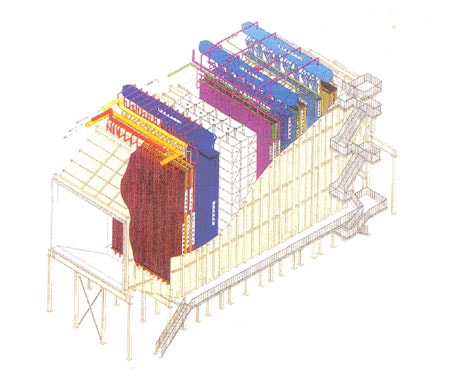
(figure 3)
5. Recovery Boilers:
These boilers are used in melting furnaces, in metalwork plants, which are installed directly in melting circuit. There is not the possibility of separating them of working system.
6. Incinerator Boilers:
These boilers are used for devastating the civic litter and generating electricity.
These boilers should be equipped whit pro and after reserves (for collecting the litter and evacuating the ash).
7. Coal Boilers:
These boilers also should be equipped with pro and after reserve for reserving coal.
Boilers Manufacturing Parts:
Each boiler consists of different parts that each one is installed for a special aim. Based on the duty they have boilers parts are divided into following parts:
Pressure Parts:
All parts in which water as steam (tubes, headers and so on) passes through, having more inside pressure than environment are called under pressure parts (figure 4). Generally, all parts from boiler feed water pump to supper-heater outlets are called pressure parts, which are listed bellow:
Main Feed Water Pipe:
transfers water from boiler feed pump outlet to economizer inlet header
- Economizer Inlet Header:
Generally it collects or distributes fluid (water or steam)
A – Distributor header: header outlets are more than inlets
B – Collector header: header inlets are more than outlets
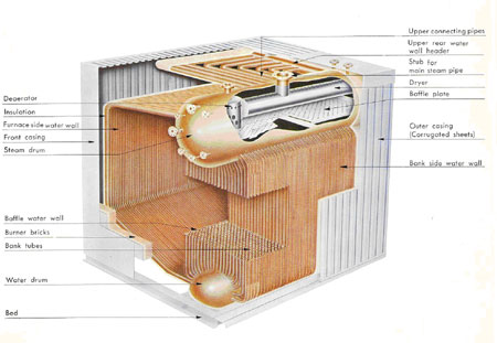
(figure 4)
Economizer Tubes:
Economizers increase boilers efficiently. Economizers increase the inlet water temperature to reach saturation, which prevents the reduction of drum water temperature. Economizers are installed in combustion gases outlet.
More heat exchange, needs more heat surfaces to maintain this fact fins are Installed on economizers tubes (fins increase heat surfaces).
The boilers burning fuel determines the use of fins. If the used fuel is from light Fuels (natural gas), the fins are used and. the fins are installed in two ways:
1. In line
2. Stager
Economizer Outlet Header:
Collects water from economizers and conducts to steam drum
Economizer Outlet Pipe:
Exchanges water from economizer outlet to steam drum inlet
Steam Drum:
Drums separate water and steam. Drums are different in structure, but all are the same in operation. The mixture of water and steam enters the separator. Then centrifugal force and circular movement will separate them.
After passing the drier plates and finally conducts to water wall tubes by down comers, steam losses its water completely. Drum is like a reserve for boilers Too. It reserves water or steam in itself and keeps it for boiler critical conditions.
Equal division of inlet water from economizer and injection of some chemical Fluids into boiler fulfills by drum.
Drums are consisting of two internal and external parts. Its main parts are:
1- Separator
2- Chevron drier
3- Drier
4- Internal pipe
Water (Lower) Drum:
Its horizontal cylindrical reserve, which is installed, in the lowest part of the boiler and acts like a header. After separation, water comes down to down comer pipes and enters the lower drum. Water drum divides feeding water equally to wall and
Bank tubes:
These tubes connect upper drum to lower drum in a way that some tubes act a sown comer and the other as riser
Water wall tube:
In modern boilers all three kinds of heat exchange (conduction, radioactive and replacement) occur, which results on changing water to steam. In these boilers use from vertical tubes as a complete wall. Water in tubes absorbs the heat energy and cools the walls.
The fins are installed between the tubes. The structure of the walls depends on combustion, steam, and boiler size.
The way of installing, the water wall tubes are as per following:
A - Boiling wall
B – Touching tubes
C – Fin tubes
The roles water wall tubes play in absorbing the needed heat for producing water and steam along with fin tubes advantages are below listed:
o Equal heat charge distribution on inner side of tubes
o Fin expanded surfaces, which reduce metal surfaces of tubes for heat absorption
o No combustion leakage from boilers
o Walls and tubes high stability
o Erection time reduction
o Walls weight reduction and easy commissioning
o Having no touch between furnace insulation and combustion products
o Increases the insulators lifetime and consequently expenses and maintenance will be reduced
o Tubes can be installed in a way that fluids speed will be proportionate to heat exchange rate
o Boiler starts to work easily by reducing the wall weight.
Not having touch between furnace insulation and combustion products makes the insulators lifetime increased in one hand and maintenance expenses will be reduced on the other hand
Making of these walls is expensive and needs much skill and experience for welding the tubes to fins. In wall tubes, water flows in tubes from Bottom to top. More water flows upward, more energy absorption and steam production we have. In natural circulation boilers because of the density differences
In forced circulation tubes between water and water and steam mixture, displacement occurs naturally. With regard to low-density deterrence, forced circulation pumps are used for circulating water. It should be noticed that just a portion of outlet water turns to steam. The amount of steam produced in boiler depends on to the boiler circulation number. In away that whatever boiler circulation number is fewer, the outlet steam amount from Wall tubes increases. It can be stated as:
Water circulation number in boiler = (outlet steam amount from water tubes)/1
For example when the circulation number is four, it means that water should turn four times in wall tubes and down comer.
Circulation number is three to ten for drum boilers and one for non-drum boilers.
Increasing the circulation number increases the boiler capacity and reduces burning of boiler tubes, which increases efficiency.
Riser pipe:
These pipes conduct water and steam from wall tubes outlet headers to drums in other words riser pipes act as an intermediate between wall header and steam drum. Connecting the pipe directly to drum increases the thickness of drum too much. To prevent this water and steam flowing in wall tubes gather in outlet headers first and then by fewer riser pipes conducted to drum.
Saturated Steam Pipe:
Conduct steam from drum to super heater inlet header.
The steam, which is heated after drum, is called dry steam with 100% quality.
Primary And Secondary Super Heater And De-Super-Heater:
Outlet steam from drum should have more temperature in order to have more energy, which is, called dry steam of super heater.
This act fulfills in super heaters consist of parallel tubes and in touch with combustion made hot gases. These pipes conduct the combustion heat.
Depend on their type; super-heaters are planned in single or multi phases. They are installed on top of the combustion chamber. They receive the heat in radioactive and displacement forms. Steam first enters the primary super heater, then de super-heater (controlling temperature) and at last, secondary super-heater should be able to keep the temperature stable in the lowest and highest turbine Load. De-super-heaters are made of two walls for preventing saturated water touch with high tempered wall. In the boilers of low temperature outlet, super-heaters are cancelled.
Re-heater:
Stem energy drops when coming out of high-pressure turbines. For preventing Moisture in low-pressure turbine, floors should conduct the energy of return Steam upward and then conduct it to middle pressures turbine. This act fulfills by re-heater. They are the same as super-heaters consisting horizontal and parallel tubes. These pipes are installed in combustion product direction. Exchange hot gases heat inside using re-heater or not depend on boiler capacity and power plant planning. Re-heaters are used just in high capacity boilers for increasing the efficiency. Re-heaters consist of two primary and secondary sections. Re-heaters parts are listed bellow:
1- Recovery cold tube
2- Re-heater inlet header
3- Re-heater tubes
4- Re-heater outlet header
5- Warm return-tubes
Main Steam Pipe:
Conducts superheat steam from outlet header of secondary superheat to turbine or heat exchangers.
Steam Air Heater:
In cold weather water particles in the air freeze when contacting to fan blades moreover, break the blades consequently. To prevent this, inlet air warms in a steam heater.
Gas Air Heater:
For preventing the entrance of low temperature air into furnace, gas air heater Issued. Since two fluids are gas with low efficiency the gas air heater are made circular. In a way, that half part of it is in cold section and half part of it is in warm section, and by turning of cold/warm blades heat exchanges.
(Figure5) pre-heater
Furnace:
Furnace or combustion chamber is a chamber which burning takes place in it. The consequent thermal energy exchanges to tubes feed water in the way of radioactive or conduction by tubes metal. The result of this heat exchanger, is to absorb the thermal energy by the water inside the tubes and changing it to steam.
Burners:
Burners turn chemical energy to thermal energy. For complete combustion, Fuel should be completely powdered in a way that particles could be more easily vaporized. Furnaces, in addition to powdering the fuel and turning it to particles, for flash vaporization of fuel and combustion make movements between fuel drops and the air.
Gas Recirculation Fan (G.R.F):
Some parts of burnt gas fumes are added to inlet air for controlling the Nox and increasing the thermal efficiency.
By using G.R.F some percentage of outlet combustion products will be returned to furnace to cover the outer surface of the tubes as a layer for preventing the tubes energy absorption in radioactive from. More increase in molecules makes more convection inside the furnace. G.R.F is more efficient in low temperature, because decreases the radioactive energy absorption in one hand and prevents overheating the superheat when starting to work.
Controlling the temperature of outlet steam from super-heaters:
A- Using De-Super-Heaters (Water Spray):
Using water spray after primary super heater decreases the secondary super Heater steam temperature. This system is necessary for boilers because of its speed and reliability. This system is planned in a way that in its real charge keeps some water spray for the time of not having real temperature because of Carbon black formation inside the tubes.
B- Angular Change Of Furnaces:
By changing the angle of furnaces, the amount of free energy in furnace of different heights can be changed. Bringing down the furnace head, increases the produced steam when reducing the steam temperature.
C- Using G. R. F:
For controlling the steam temperature when starting to work, some amounts of Outlet gases will be sent back to furnace by G.R.F.
Incinerator Boilers:
Ever increasing production of garbage and inappropriate ways of gathering made the thermal plasma process a proper method for burning the garbage.
Plasma:
Plasma is one of material forms. For the first time Dr. Long Muyer an American Chemical physician scientist in 1929 called the ionized gas as plasma.
It consists of a set of atoms, ions and electrons, which move freely. Electric and magnetic fields will affect plasma.
Plasma System For Garbage Disposal:
All plasma system has five main parts:
1. Feeding part
2. Combustion chamber
3. Outlet gas processing unit
4. Gathering solid products
5. Lateral equipment
Garbage enters the feeding unit. Then in appropriate portions, it will be put into furnace. Plasma gas, which is heated to near the sun heat, will be transferred to garbage. Plasma heat can be transferred in radioactive, convection and conduction forms garbage decomposes to raw and simple material by Pyrolisis method. Main part of outlet gases are hydrogen and carbon monoxides and acidic gases like HCI and h2 s. in plasma technology there is no need to oxygen and any oxygen reserves and its thermal out come is two to three times more the fossil fuels thermal outcome.
Boiler planning and engineering department field of activities:
- Planning of industrial and power plant natural circulation water tube boiler packages with 20-t/hr capacity and more steam production based on customer demand.
-Technology transfer contract with IHI Company from Japan based on manufacturing of water tube boilers with natural circulation burning with gas and fluid fuels as Per followings:
- Package boilers from 20t/hr to 100t/hr capacity
- Industrial boilers from 50t/hr to 350t/hr capacity
- Power plant boilers from 390t/hr to 2200t/hr capacities
-Technology transfer contract with Gadelius K.K for Langstorm pre-heaters
- FW combination cycle
Different kinds of power plant, industrial and equipment manufactured in AzarAb Company
Boiler Type Choice:
Water tube boilers are AzarAb main products and AzarAb is one of the greatest boiler manufactures in Middle East. We are able to manufacture different types of water tube boiler, from 20t/hr to 2000t/hr under the licensee of I.H.I form Japan.
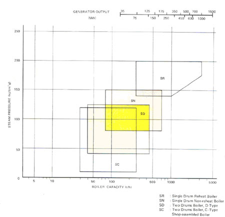
(Figure 6)
1) Base Heating Power Plant Steam Boilers:
This kind of boiler consists of a natural circulation drum, super heater and economizer. The air direction is toward furnace. This compound boiler consists of furnace and heat recovery zone. (Figure 7)
AzarAb has installed in Shahid Rajai power plant a MW 250 model in which consists of 12 furnaces in front wall and eight furnaces in back wall. Outlet gases pass two parallel directions in which one of them consists of re-heaters and the other consists of super-heaters.
Heat gases passing the parallel directions exchange the heat to re-heaters and Super heaters join each other, then pass the primary economizer and enter the air pre-heaters. Duper will control re-heaters, which are installed at the end of re-heaters outlet steam temperature from re-heater, and re-heater and Super-heater dampers generator high changes are set in a way that outlet steam Temperature remains stable.
Advantages of controlling re-heater by dumber are as less consuming power, better re-heater protection, and fast response to re-heater temperature changes.
Re-heaters main duty is to increase outlet steam temperature from H.P. turbine.
The boilers drum is located in upper part and along the width of boiler.
Separating signs separates the water and steam mixture entering to drum from wall tubes (risers).
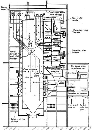
(Figure 7)
Mentioned Boilers Specifications:
Produced steam capacity 390 to 2200 t/hr
Planned pressure amount 150 to 2000 kg/cm2
Its fuel bused on its facilities can be natural gas or mazout.
2- Stable Boilers (SN):
These boilers under the I.H.I certificate are manufactured for industrial and Power plant purposes. They are single drum non-heat-recovery, natural circulation and radioactive heat transfer .the used fuels can be natural gas mazout or gas oil.
- Produced steam capacity 90 to 950 t/hr
- Planned pressures amount: 80 to 150kg/cm2
(Figure 8)
3- Stable Boilers (SD):
This kind of boilers because of their high quality and efficiency has special Situation between industrial and power plant boilers.
With a stable structure, consist of two water and steam drums with natural Circulation fluid, a large furnace for complete combustion and high temperature control super heaters.
Boiler more specifications:
Produced steam capacity 40 to 420 t/hr
Planned pressure amount 40 to 110 kg/cm2
Maximum temperature 515 c (960 f)
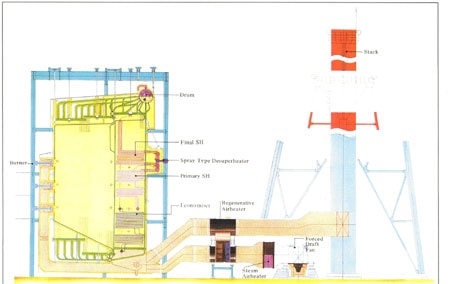
4- Water Tube Boiler (SCM):
For better maintenance, these boilers consist of two drums and heat exchange is done by furnace in convection and radioactive ways.
(Figure 9)
Here the preheated water conducts to water and steam drum installed in top of the boiler and then goes to all tubes and pipes. Contrary to type 1, this boiler has no heat recovery system. Water walls with two or 2.5-inch outer diameters are completely welded for using in replacement units.
For regulating the water level in drum, there are special signs under the usual Water level. In this way, the dryness of the steam will be kept more than 99.5 Percent.
BOILER MORE SPECIFICATION:
- Produced steam capacity: 5 to 35t/hr
- Planned pressure amount: 10 to 25kg/m2
Mazout is the used fuel.
5- Pre-Made Boilers (SC):
Contrary to other boilers, these boilers will be transported and installed in the site after manufacturing and installing it in the workshop as a complete pre-mode unit.
There are some limits in dimensions and weight of these boilers because of Traffic regulations.
MORE SPECIFICATIONS:
- Produced steams capacity 250 t/hr
- Planned presser amount: 30 to 350 kg/cm2
- Maximum temperature 48c (900 f)
The used fuels are gas or gas oil and/or a mixture of both.
(Figure 9)
Boilers Lateral Equipment :
1- Gas and air canals
2- Gas and air regulating valves
3- Gas and air expasile Canal openings
4- Inlet air preheating by steam and water
AzarAb manufactured all these equipment.